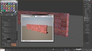
Undocumented feature of VRayLensEffect
About the feature
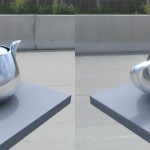 This post is about a not well (if at all) documented feature of VRay 2.3, more specifically of the VRayLensEffect render effect. Before I discovered this feature, it was very hard to tune the lens effects produced by VRay and almost all of my images were extremely blurred and shiny, which forced me to do those effects in post production.
The official VRay documentation on spot3d.com - especially the one for 3D Studio Max - does not talk about the masking possibilities of the VRayLensEffect, but in fact, this feature ultimately makes the VRayLensEffect useful!
What it does
VRayLensEffect has its own render channel: the LensEffectsSource. This unclamped channel is the base for all lens effects (Bloom and Glare) applied to your rendering. In nearly all scenes I used lens effects for, this channel was absolutely overbright, resulting in a extremely blurred image after VRayLensEffect had been applied to my renderings. Since VRay 2.3 we can overcome this fact by telling VRay to use only parts of this channel for lens effects. This is called "masking". Masking means that the lens effects are only applied to pixels with a float value above the given mask value while ignoring pixels which are not bright enough and have a lower float value.
How to use it
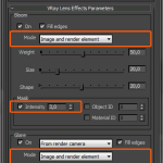 Step 1
First of all, we need to render out an image - draft quality is enough - with the options checked like shown in the screenshot to the left.
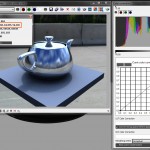 Step 2
The next step is to check the float values of the LensEffectsSource to set up mask parameters. Pick the light source in your rendering (or the light's reflection in your object) with the color/pixel picker (rightclick on your rendering while using Vray Frame Buffer) and set the mask parameter to the lowest of the float values in the "Pixel information" window (or a slightly lower value). Render again.
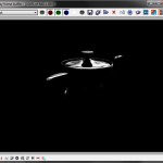
 Step 3
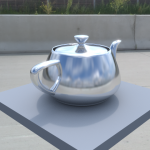
You can check the GlareMask and BloomMask channel after the rendering has finished. Tune your VRayLensEffect parameters and your render settings and render again.
Looks better now, doesn't it?
That's it!
I hope this will help some of you and save you the time to fiddle around with the settings until it looks nice. By the way: the HDRI used in this little rendering is from our product scout Andreas Reimer. Thank you Andreas!
GrowFX 1.8.6 tutorial
Understanding the basics
GrowFX seems to be really complicated when you try to make your first tree from scratch. Indeed, it is a lot easier if you understand the basic concept.
Think of a small tree. It's made up of different sections. For example it starts with roots forming the trunk, which has some branches, which have some smaller branches on which there grow some leafes. Every section – regardless which one - can be split up into three parts:
- Source (Where do the section elements grow from?)
- Behaviour (How does the section behave?)
- Appearance (How does the section look like?)
GrowFX splits these three parts into three seperated windows: Distributors path, Modify direction and Mesh parameters. A section is called „path“ in GrowFX terms.
Getting started
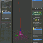
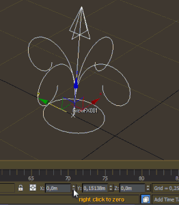 Start with a blank scene. GrowFX generates extremely realsitic trees and plants, which leads to lots of polygons and may slow down 3D Studio Max a lot. You can move your tree into your original scene later as soon as you finished it. Click and drag a GrowFX object/icon into your viewport. Move it to the origin (right click on each of the axis' spinner arrows on the bottom of your screen to set them to zero).
First section
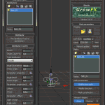
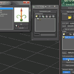
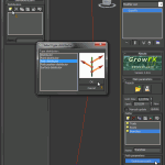
Create a new path and name it „Trunk“. (You should always rename your sections to stay on top of things!) You will first notice that you can't see this path inside your viewport. That's because we didn't specify the source. Click on „Distributors path“ while you have the „Trunk“-section selected. This „Distributors path“ window lets you choose from different distributors and every distributor has its own meaning. Since we want the trunk to come out directly from the GrowFX icon, we select the first distributor. Most of the time the small image next to the selection list shows exactly what each selection does. Now we can see a straight line coming out of the GrowFX icon. We can now close the „Distributors path“ window and leave everything to its defaults. We finished the first part of our section: the source.
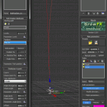
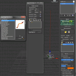 Now it's time to determine the behaviour of our section: the second part. The trunk is relatively easy to control. Open the „Modify direction“ window. Here you can control the section's length and direction. Add a direction modifier and select the „Random direction“ modifier. This will add some natural feeling to our tree. Play with the random direction parameters „Smoothing“ and „Angle max“ until you like the look of your trunk. If you want your tree to bend a little bit, you can add a „Vector direction“ modifier on top of your „Random direction“ modifier and play with the „Strength“ parameter. This was the second part.
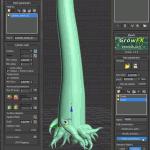
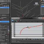
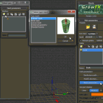 The third part (Appearance) is the last step for this section. Until now we just have an irregular line which does not look like a trunk. We need a mesh, so open the „Mesh parameters“ window and switch the „Viewport display“ from „Lines“ to „Meshes“. Create a „Cylinder mesh“ to form a trunk-like mesh for your path. Set the maximum „Radius“ of your trunk. I chose 30 centimeters (0,3m) in the example. To control the overall look of your trunk, click the graph icon next to the spinner. This opens another window containing a graph. The very left shows the start of your path, the very right shows its end. So from this graph we can read that the trunk starts at 0,3 meter and ends at 0,0 meter, which creates a linear, conical trunk. You can play around by adding some points, but don't get too nasty.
 ![]()
Now we are done with the first section. Congratulations!
Second section
I know. A tree does not start with the trunk, but with the roots. That's true for reality but not for 3D in our case... Create another path (section) and name it „Roots“. Inside the „Distributors path“ window, we add a „Path Position Distributor“ and select our „Trunk“ path as „Starting path“ and add a new position. We want to see some roots off the ground, so we set the „Absolute Position“ to 0.3m and change the number of roots to about 20. Scroll to the bottom and set „Angle bend“ inside the „Start vector“ group to -180. Now our roots are growing into the ground. Add a bit of „Chaos“ to the point offset if you like. Close this window and switch over to the „Modify direction“ window where we add a „Vector direction“ and a „Random direction“ modifier. Play with these parameters until you like what you see. You can also change these parameters after the next step: the appearance. Open the „Mesh parameters“ window and switch the viewport display to „Meshes“. Add a „Cylinder mesh“ and change the parameters in the same way we did with the trunk section.
Okay. This looks a bit strange for now. But let me tell you: we will boost this in the end with a very unique feature of GrowFX, the so called „Meta mesh“. If you can't wait: here you go. ![]()
Third section
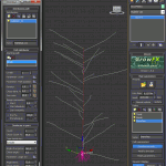
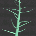
What's next? The branches! You should be able to easily add them by yourself now if you understood the last chapters. Most of the steps should be self-explaning now. One difference is the distributor. We will choose a „Path distributor“ because we will add lots of branches connected to our trunk path. If you don't want branches to grow at the bottom of your tree you can set the „Start“ parameter inside the „Range parameters“ group to something above 0,0. This way GrowFX doesn't create branches below a certain point. Another solution is to change the graph of the „Density“.
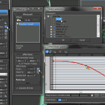 One thing that confused me when I started to use GrowFX are „Affectors“, editable by clicking these icons:
 ![]() . Those affectors are very powerful. Let's take a look at „Parameter: Path position“. Read it like this: „the position on the path affects...“. We want something like this: the closer we get to the top of our tree, the smaller the branches should grow - just like in nature. So we choose „Parameter: Path position“, add The length of our branches to the affector and change the graph of the „Factor“ parameter inside the „Affect factor“ group. This leads to a nice looking tree shape.
. Those affectors are very powerful. Let's take a look at „Parameter: Path position“. Read it like this: „the position on the path affects...“. We want something like this: the closer we get to the top of our tree, the smaller the branches should grow - just like in nature. So we choose „Parameter: Path position“, add The length of our branches to the affector and change the graph of the „Factor“ parameter inside the „Affect factor“ group. This leads to a nice looking tree shape.
Fourth section
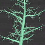
This is where you will add some more branches on top with the branch's path beneath. Play around and have fun!
Fifth and last section
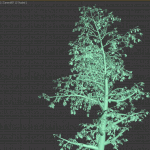
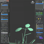 Even if you could go on adding more sections, we will finish our tree with some leaves now. Each type of tree has its own growth behaviour for leaves. We will take a simple approach to put some foliage on our tree. Add a new path called „Leaves“ and add a „Path Position distributor“. First, we will add the trunk as „Starting path“ and add more sources later. Add a „Position“ and leave its parameter at 100% which means we put our leaves at the end of each branch. Change the „Count“ to about 3. Change „Type distributor“ from „Circular“ to „Angular“ and the „Angle divergence“ to 90 for a more leaf-like angle.
For the leaves' behaviour we add a „Random direction“ and a „Vector direction“ modifier in the „Modify direction“ window and adjust the settings.
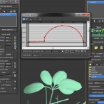 Now to the fun part: the mesh. You can create almost every possible leaf with GrowFX. Just add a „Leaves mesh“ in the „Mesh parameters“ window and edit the graph of the leaves' length parameter. Lean your head to the right while looking at the graph. Do you get it? Yes, this is the shape of a leaf cut in half with its stem included! Cool, isn't it? ;o)
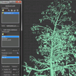 If your leaves look right, just add the other sources to the „Starting path“ list in your leaves' „Distributors path" window. You can also add another „Path distributor“ to your leaves and select your small branches as a „Starting path“ to get more leaves.
Materials and textures
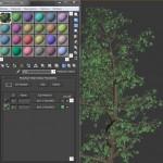
Another great feature of GrowFX is its ability to automatically generate perfect UV coordinates for texturing. First, open the material editor of 3D Studio Max and create a new „Multi/Sub-Object Material“. Set the number to 2. In the first slot we put a brown wood material, in the second one we put a green leaf material. Assign it to your GrowFX tree. It looks much more like a tree now! And GrowFX created really nice UV coordinates for us which don't really need any tuning... Nevertheless, I'll show you how to tune the texture coordinates if you still like to do so.
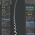 Switch off everything but the trunk by clicking on the yellow light bulb next to the paths and switch over to the „Mesh parameters“ while „Trunk“ is selected. Press the „UVW Mapping“ button and check „Absolute width“ and „Absolute length“ as well as „Scale length by Radius“ and adjust the „Width“ and „Length“ parameters as needed. Use a „Checker“ texture inside your trunk's material to check if your parameters are just fine. Go on with the the rest of your tree and activate one section after the other.
Fine tuning
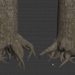 Okay. We now have a tree. But does it look realistic? Not really. Let's unleash the power of GrowFX! Disable everything but the trunk and the roots. Open the „Mesh parameters“, copy the „Cylinder mesh“, paste it and deactivate it. Right click on the new one and choose „Convert to Meta mesh builder“. GrowFX generates the Meta-/Blobmesh from trunk and roots. This should go quite quickly. Do the same steps with the branches. This will take far longer to calculate, but if it's done you can navigate as fast as before. If you want to take this another step further, get a cup of coffee after repeating the Metamesh conversion with the small branches. Go out, have some fun with your dog or your kids, whatever you like to fill the time GrowFX needs for calculations. It will take very long and most of the time it's unnecessary to bring that much details on your trees! But what exactly does this magic meta mesh do? It's melting together your meshes into one mesh, building an enclosing mesh like the surface in nature. Your cylindrical parts don't stick into each other, they get one mesh.
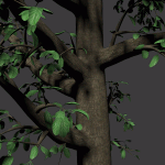 Some other things you can do is to rise the „Min sides“ and lower the „Min radius“ and „Face size“ parameters all over the different windows to get more detailed meshes and smoother paths. It may be very essential for your leaf meshes to look good.
Useful tipps
- It's always a good idea to disable sections/paths if you don't need them to speed up calculations.
- Do also use „Lines“ in the „Viewport display“ to speed things up.
- Always keep the „Cylinder mesh“ in addition to your „Meta mesh“ and only switch to this mesh type before you export your final tree.
- Make a copy of your tree scene before you convert the tree/plant to a mesh
- Save a VrayProxy or other kind of Proxy mesh to speed up renderings
Where do I get GrowFX?
 You can buy GrowFX directly here on zwischendrin.com in our scripts & plugins section for 240€!
MightyTiles tutorial – first steps HowTo
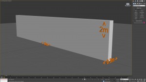
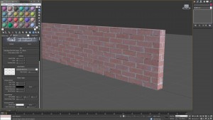
Let's start with a box. Make it 10m x 2m x 0.3m in size.
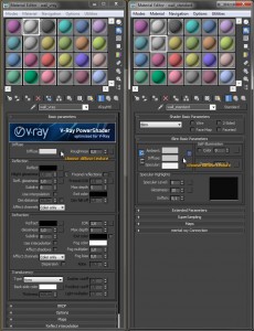
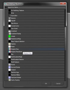
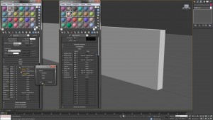
Assign a material to your box and click the button next to the diffuse color. The image shows a VRay material on the left and a Standard (Scanline) material on the right. Choose the 'MightyTiles' texture from the Material Map Browser.
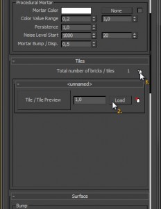
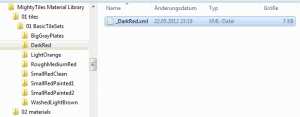
The MightyTiles texture window will now open inside the material editor. Set the 'Aspect ratio' to 1.0 and scroll down to the 'Tiles' rollout. Add a new tile set (1) and load one from the material library available with MightyTiles (2).
I chose the 'DarkRed' bricks set for this tutorial.
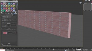
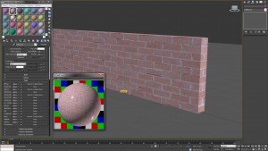
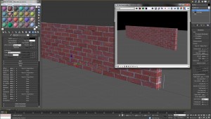
You can see that our bricks look stretched. This is because our texture coordinates don't fit. One of the very first things we did was to set the 'Aspect ratio' to 1.0 which means the width and the height of our texture coordinates have to be the same size. The automatically added UV coordinates of our box do not fulfil these needs so we add a modifier to the mesh.
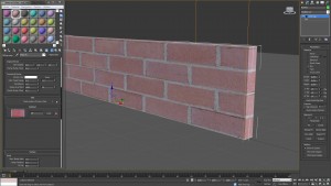
This is how it looks after adding an UVW Map modifier. Change the gizmo of the modifier until you are satisfied with the result.
It's now time to change the number of bricks by changing the 'Rows' value in the 'Common' rollout of our MightyTiles texture. I chose 50 rows.
MightyTiles doesn't just bring you diffuse textures. Every tile set has all the needed chanels included as well and even recognizes the corresponding map slot! You just need to drag & drop the MightyTiles texture to each slot and and choose 'instance'. The left material editor window shows a VRay material, the right one is for a Standard material.
You can now tune the maps directly inside your material or inside the MightyTiles texture. I tend to use the first method because it seems to be much quicker.
As you may have noticed, our texture looks a bit washed out. We can handle this by adjusting the 'Gamma and LUT setting' of 3D Studio Max. Set the 'input gamma' to 2.2 and MightyTiles will automatically adjust the brick texture.
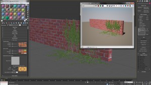
The bricks now look much more realistic. We do now add some displacement to our wall by adding a VRayDisplacementMod to the stack of our box. After we've done that, drag & drop the MightyTiles texture into the 'texmap' slot of the displacement modifier and adjust the settings to your needs.
MightyTiles has very nice randomization parameters, making it possible to create extremely huge textures without visible tiling effects, such as position, rotation, scale and also hue, saturation and value.
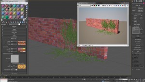
This is what I came up after some parameter adjustments. By the way: MightyTiles didn't create ivy ![]()
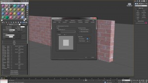
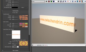
If you want more control over your texture, MightyTiles can even add 'Image Based Color Control' to directly modify the colors of your bricks with a texture and create a mosaic effect.
To change bump, displacement and reflection values randomly, you can adjust the corresponding values in the 'Surface' rollout.
I hope this will help you understand MightyTiles and I wish you loads of fun with this great plugin!
How to create HDRI panoramas with VR Drive 2 and AutoPano Giga
I thought it would be cool do write a tutorial on how to shoot and stitch an HDRI. Maybe it helps our scouts or someone else trying to produce HDRI panoramas.
A little backgound information:
The new Roundshot VR Drive 2 is a great tool and everyone who owns this piece of hardware is really looking forward to an upcoming feature called "HDR mode". This firmware upgrade will enable you to shoot HDR panoramas with a single click on a button. This mode is currently under development and until now a release date is not in sight.
So what to do until this mode gets released? I will tell you how we to it.
You have to shoot several panoramas, each with its own exposure settings. This makes lots of images. 18mm lense, 1EV steps, 15% overlapping with a Canon 450D makes about 288 pictures. More pictures would lead to higher dynamic range but that should be good enough for most of our purposes. The process of taking these panoramas is simple. You set an exposure on your camera and wait until the VR Drive 2 is ready with shooting. You change the exposure and repeat these steps until you captured as many panoramas as possible.
Ok. Now we got lots of single images. Now comes the "fun" part. ![]()
We don't want to stitch them manually, of course. So we take AutoPano Giga, a great software for stitching panoramas. Although AutoPano does a good job on that, a new problem arises: overbright images. Even the best software can't generate links between images if the images are pure white. This often happens when you take an HDRI outside and the sky is really bright.
Here is a really nice workaround: we create HDRIs for each tile/picture of the HDR panorama. In our case we get 32 single HDRIs which we stitch together in AutoPano (yes, AutoPano can even stitch HDRIs from HDRIs!).
"How to create these HDRIs? Do you bracket photos after shooting?" Yes. I wrote a little application that detects photos inside a folder and sends them to Picturenaut. Picturenaut is a free software that can merge LDRIs (standard photos) into HDRIs and even tonemap those HDRIs. We are only interested in one part of Picturenaut called MKHDRI, a command line tool to make HDRIs. I will release my little application soon, so stay tuned!
Now we are ready to stitch. We have 32 .hdr files and want to feed them to AutoPano. One little step makes this a lot easier: do exposure corrections! Don't fear, you will not make any defect to your HDR images. Don't tonemap them! Just correct them to look neither too overexposed nor underexposed. Open AutoPano and let it automatically stitch your images together. If this is done use the following settings to render out your HDRI panorama:
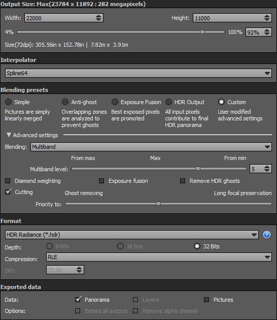 Theses settings are essential! I tested lots of settings and came out with these. The Multiband level can be changed if you like but 5 seems to be great. Width and Height are linked to your panorama, of course.
 ![]()
If your panorama stitched nearly perfect you should save it as a Template (File -> Save as Template) so your next panoramas (with 32 single HDR images) will have less faults.
Your HDRI panorama is ready to get retouched! Use your favorite image editing software to correct the nadir and things like that and you will get a perfect HDRI. Have fun!
A quick SnowPrint tutorial
This short video tutorial will show you how to use SnowPrint, a special feature of SnowFlow 1.8
